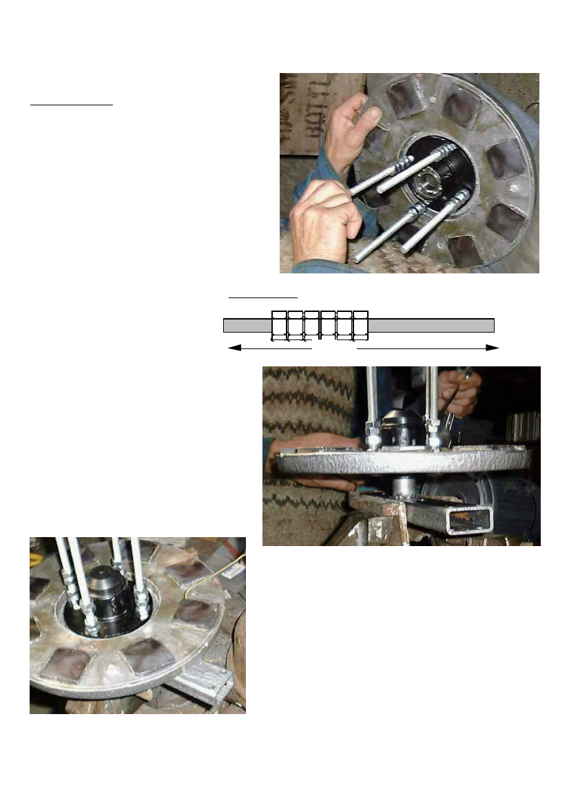
Photos show the rear magnet rotor being fitted
PMG assembly
• Cut 4 pieces of M10 threaded rod,
each 200 long. They are used as
studs to hold the magnet rotors to
the hub. The wind turbine blades
will also mount onto these studs.
• Put 6 nuts onto each stud) see
diagram 41).
• Fit the studs through the holes in the
bearing hub, from the front
• Put the rear magnet rotor onto the
ends of the studs.
• Put a nut on the end of
each stud, and tighten the
other nuts down, so that
41. STUDS
the rear magnet rotor is
attached to the back of
the hub flange. The outer
end nut should be sealed
with paint or thread-
sealant.
• Place the spine in a vice with the
shaft upward. Place the hub onto
the shaft. Do not hammer the
magnet rotor while fitting.
Fasten the hub to the shaft with a
nut and split pin. Do not over
tighten the nut. Fit a dust cover
over the end of the bearing hub.
THREADED ROD
200mm
10mm
PMG manual
• Rotate the magnet rotor past a piece of
brass wire. Do not use steel wire, because
it is attracted to the magnets. The magnet
faces should all be at the same height +/-
0.5mm. If not, use very thin shims between
hub-flange and rotor-disk, to adjust the
rotor.
• Using a spirit level, adjust the spine in the
vice until the magnet rotor is level. Check
both ways: north-south and east-west.
• Take the stator. Fit one 8 mm nut onto each
support stud. Screw them right down.
page 38
June 2001